A diaphragm compressor is a most famous type of the compressor. A diaphragm compressor uses a set of three flexible diaphragms to move (and compress) the gas. The air goes in the process head of the compressor from the external tank or the down-stroke of the process. On the upstroke, the diaphragm flexes, decreases the space in the compression cylinder and discharges the compressed air out of the compressor. This compressor uses a hydraulic pump to inject the oil in the hydraulic system. The crankshaft drives to this pump.
The vibratory motion of the diaphragm drives via the rotating piston and the crankshaft mechanism. Only the process diaphragms and the process head of the compressor make contact with the air. This contact is compulsory because the membrane prevents hydraulic oil (or compressor oil) from coming into contact with the process air. This avoids potential gas pollution which is essential for hydrogen purposes as the purity of the working air has a direct effect on the procedure. Due to this characteristic, diaphragm compressors are best suitable for transferring explosive and toxic gases. The membrane should be adequate reliable to withstand fatigue while having sufficient corrosion-resistant chemistry.
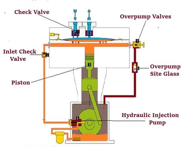
Working of Diaphragm Compressor
The working cycle of the diaphragm compressor begins when the diaphragm group is completely deflected to the bottom of the cavity under the action of the suction pressure of the process. The hydraulic piston is at bottom dead center (BDC) and the hydraulic system has just received hydraulic oil from the single stroke of the injection pump.
On the process side of the membrane, the cavity is configured to fill with process gas at a given suction pressure level and the process gas enters through an inlet check valve. As the crankshaft rotates and the hydraulic piston moves from BDC to top dead center (TDC), the oil in the cylinder head rises. This happens because the injection and return lines of the hydraulic system are blocked by the one-way hydraulic valve and the hydraulic over-pump valve.
If the piston remains aligned in the TDC direction and the oil reaches the process gas pressure level in the cavity, the membrane sweeps over the cavity in the TDC position and compresses the process gas. When the process gas pressure in the cavity reaches the pressure level behind the outlet check valve, the check valve opens and the process gas is released from the cavity.
The piston needs a certain stroke to reach the TDC position, even if the diaphragm is in a completely different pressure position. When the piston moves to TDC, the hydraulic over-pump valve compresses an additional amount of hydraulic oil, the valve pressure level is higher than the required process gas outlet pressure, which ensures an efficient total volumetric head. At this point the compressed portion of the loop is complete.
The hydraulic piston is currently moving towards BDC. The expansion of the exhaust gas in the volume of the room and the additional pressure of the suction gas entering the cavity through the check valve cause the membrane to deflect towards the bottom of the cavity. During the suction stroke, the crankshaft-synchronized auxiliary eccentric cam hits the plunger of the hydraulic jet pump.
The amount of hydraulic fluid injected is approximately equal to the amount of hydraulic fluid lost through the hydraulic over-pump valve at the end of the compressed portion of the cycle. When the hydraulic piston reaches the BDC position, the hydraulic system is refilled with hydraulic oil. The diaphragm package is in the BDC position to ensure that the air can is filled. This completes the cycle.
Components of Diaphragm compressor
1) Check valves
Set the check valve according to the operating condition and the working medium. Valves can easily be checked, repaired and replaced.
2) Hydraulic piston
The hydraulic piston is used to pressurize the membrane. At high pressure, unpacked and ring-less pistons turn into a sharp, hardened sleeve.
3) Hydraulic over-pump valve
Controls the pressure in the hydraulic system. The movement of the spindle-ball-spring combination determines the pressure range of the valve.
4) Over-pump sight glass
Visually shows hydraulic fluid in the piston.
5) Hydraulic injection pump
This is used to inject fluids in the hydraulic system.


Stay connected